Purpose
Primary Injection Test Set DTE-10M (High-Current Circuit Breaker Test Device)
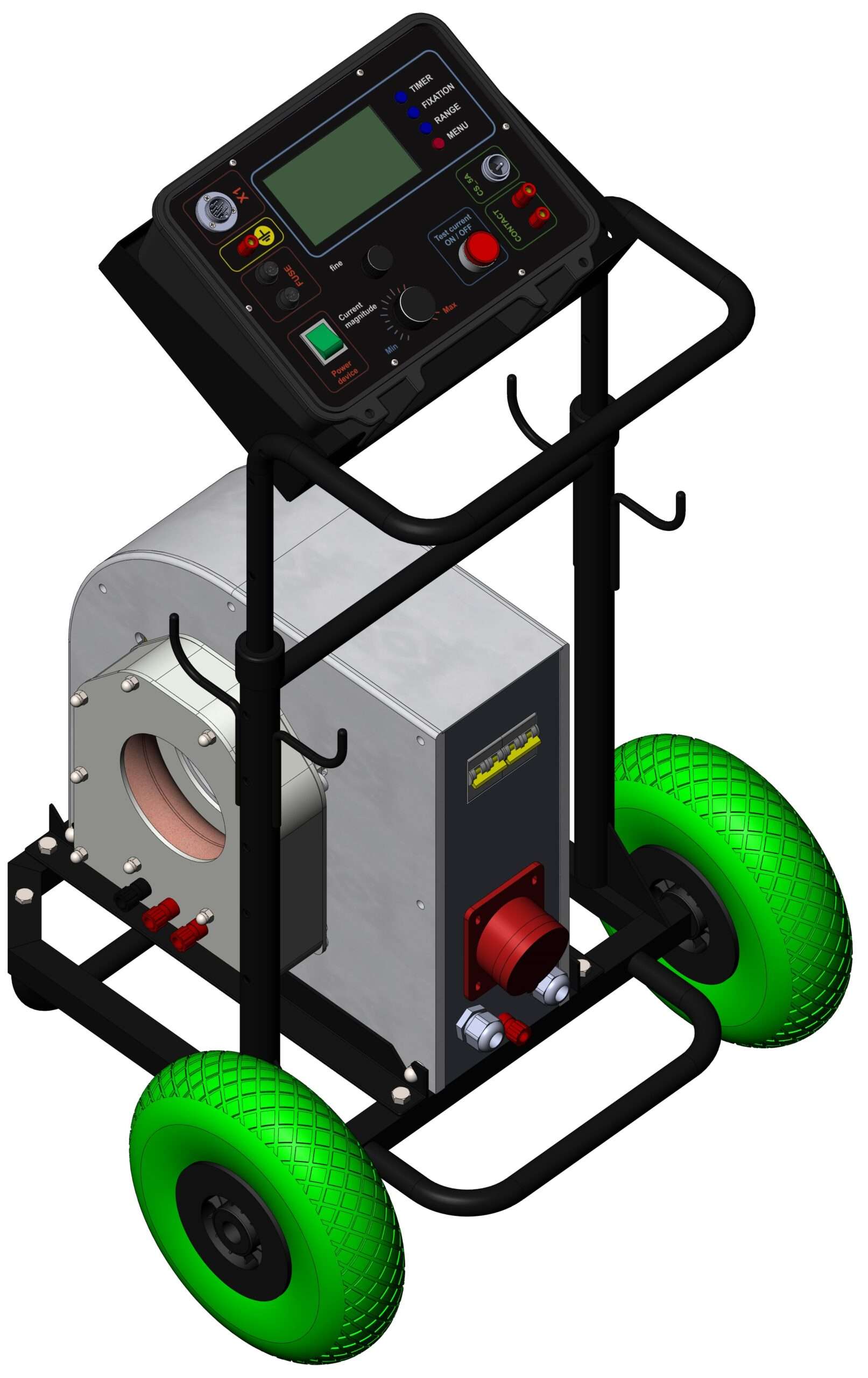
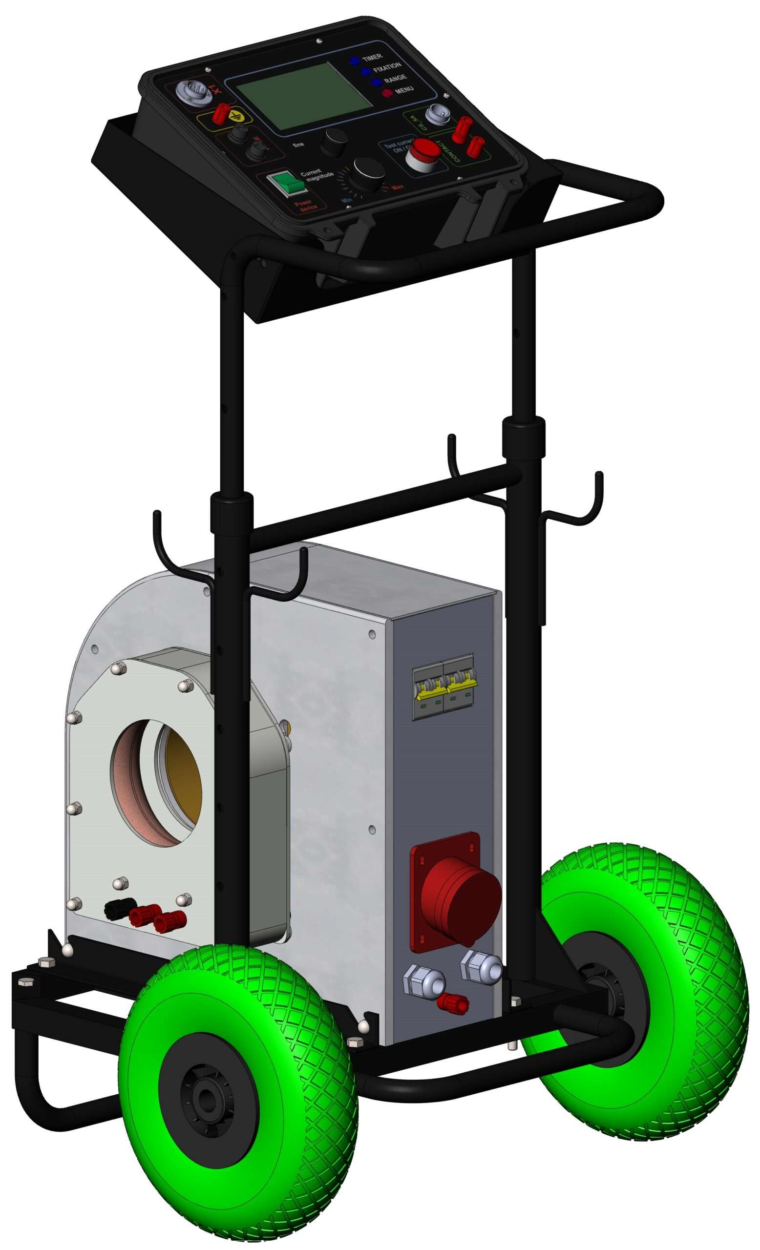
The DTE-10M Primary Injection Test Set is an advanced high-current circuit breaker test device designed for verifying the performance and time–current characteristics of AC circuit breakers in the extended range of 20 A to 10,000 A. This equipment measures and records both current and operating time of the circuit breaker under test, making it especially suitable for testing powerful breakers, heavy-duty power circuits, and utility equipment.
Main Applications
- Circuit breaker testing (verification of time–current characteristics up to 10 kA).
- Primary current injection testing and certification of measuring and protective current transformers.
- Relay testing and calibration, including industrial overcurrent and thermal relays rated for high currents.
- Fuse testing and verification of high-capacity fuses.
- Use as an adjustable AC current source up to 10 kA in low-impedance laboratory or field circuits.
Key Features
- Portable high-current test set – designed for laboratory, industrial, and field applications.
- Galvanic isolation of the output circuits from the power supply ensures maximum operator safety.
- Wide testing range – one device covers circuit breakers, transformers, relays, and fuses up to 10,000 A.
- Extended capabilities compared to the DTE-3M and DTE-6M models, making it ideal for testing powerful and high-voltage electrical equipment.
Price on request.
Contact us to buy the DTE-10M Primary Injection Test Set directly from the manufacturer and get detailed information about delivery and availability.
Technical specifications
| *Supply Voltage, V | 400 ±5% |
| Supply Network Frequency, Hz | 50 ±1% |
| Maximum Voltage on Output Buses, V | 2,4 |
| Maximum Current on Output Buses (RMS), A | 11000 |
| Maximum Power Consumption DTE-10M, kVA | 77 |
| **Range of True RMS measurement and recording of the output current, A, from 10% to 100% of the selected range with a stated measurement error of less than 3%. | 20 – 11000 |
| Measurement and Registration Range of Output Current Duration, sec, with measurement error less than 1.5% | 0.01 – 9999 |
| Threshold of Power Transformer Overheat Protection, °C | 80 ±10% |
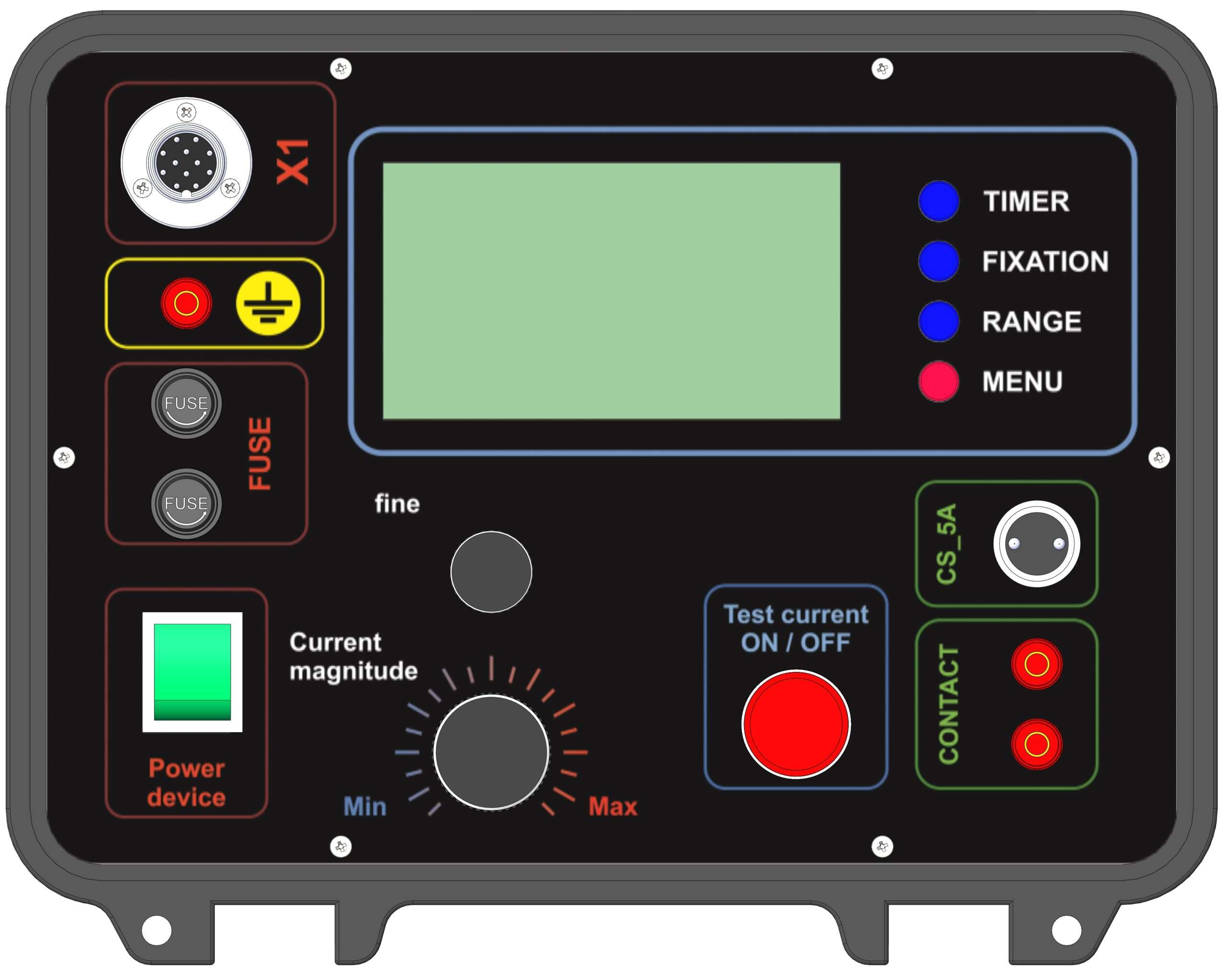
| Overall Dimensions of Control Unit BU-10, mm | 300×250×135 |
| Overall Dimensions of Current Amplifier Unit BPS-10, mm | 480×250×320 |
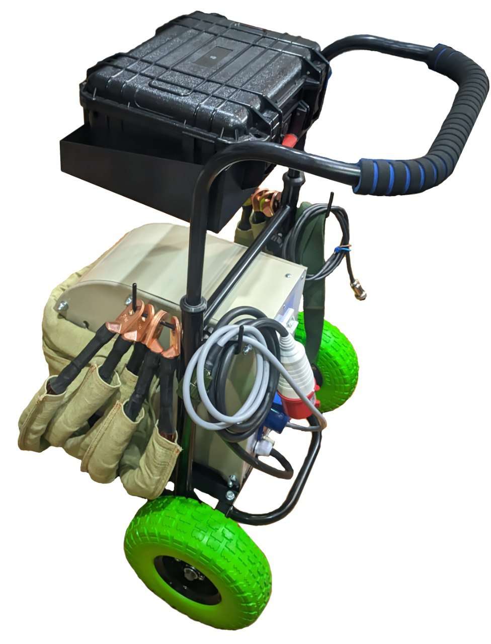
| Overall Dimensions of Transport Cart, mm | 420×220×780 |
| Mass of Control Unit BU-10, kg, max | 3.6 |
| Mass of Current Amplifier Unit BPS-10, kg, max | 40 |
| Mass of Current Sensor DS-10, kg, max | 3 |
| Mass of Transport Cart, kg, max | 12 |
| Average Service Life of the Device, years | 10 |
* The device can be powered from a voltage of 230V, while the maximum output current = 6kA.
** The technical characteristics correspond to the given values when operating the device complete with a single-phase voltage regulator (SVR).
Device operating conditions
| Environment temperature range | -5°C — 35°C. |
| Relative air humidity at +25°C | ≤80%. |
| Atmospheric pressure, mm Hg | 630—800 |
You can see the 3D model of the device at this link
Gallery